Punch Design Patterns and Reference Architecture
This track provides guides/references for some deployment/configuration patterns that answers to frequent use-cases or system requirements
The dual-site synchronization/Disaster management pattern for central sites
The problem
This pattern is an answer to this kind of system requirement:
Disaster recovery/global failover requirement
In case of major disaster or other cause of unavailability of the back-office/central/main site, it shall be possible to resume quickly the service/operation using a secondary site, with consistent,recent data and the same level of capabilities.
First let's suppose that "the same level of capability" implies that we'll have about the same hardware VMS/CPU/RAM on the secondary site, to deliver the same level of features and performance (including handling new real-time incoming data for a time period that may exceeds days or weeks).
So the hardest design decisions to tackle relates with:
- The "availabilty/freshness" of data on the secondary site, after the failover (in particular, the data coming from operator decision/action on the main site)
- The risk of duplicate outputs in nominal operation if we choose a dual-active design for at least part of the feature (e.g. the cyber rules alerts)
- The risk of "split-brain" (ie. the secondary site thinking it is in a failover situation, and 'diverging' from the main site date, so as to prevent any data re-synchronization)
The alternatives?
To tackle that, there are roughly the following main alternatives:
1) Active/off with no replication
The secondary site is normally processing nothing and does not have a copy data from the main site (to gain storage hardware costs and energy costs on the secondary site in normal situation).
It receives periodic snapshot of the main site data, but in case of failover, will lack the most recent updates. In normal situation, it does not generate any duplicate output (alerts, processing results) as it is not processing any real-time entry
Upon failover: - we have to start up the full system (except if it is running, which has energy costs implication) - we activate input flow delivery/processing on this secondary site instead of the usual one. - Some detection rules based on intra-day/past real-time data may take time (hours) before they can fully operate nominally. History data from the primary site may be optionally restored to the secondary sites in days(at least to previous day status) if such backup still exists in the disaster context, and if the hardware of secondary site allows such storage/import.
At the end, intra-day history of the failover day will never be available (except if external subsystem is able to provide and inject again the intra-day full flow, AND we have sufficient additional CPU/RAM on the secondary site to handle this reinjection in addition to the real-time flow).
2) Active/standby with daily replication
The secondary site is normally processing nothing and does not have a copy of real-time data from the main site. It receives periodic snapshot of the main site data, but in case of failover, will lack the most recent (intra-day) updates.
All limits and gains are the same as 1), except that - we need some snapshotting mechanism on first site, that produces consistent export data. This may require additional hardware resources at the main site (export filesystem), and some automation. Disaster can occur DURING the snapshot building, so resources must allow that the previous day data is already safe on the secondary site while we try to build a new snapshot. - on secondary site, depending on the export/synchronization process, we may need some energy/cpu to daily import/index the data snapshotted from the main site, to ensure it is easily available in case of failover (e.g. we cannot reinject 1 month of history compressed in gzipped flat files into Elasticsearch instantly: indexing takes resources).
Hint
For this kind of synchronization, infrastructure-based replication can be applied as long as the sizing and layout of filesystems is the same on the two sites (i.e. same number of servers/Vms/partitions/filesystems), as it may reduce the energy/monitoring/failover-latency costs related to having an application-managed synchronization (e.g. import of Elastic snapshots)
3) Active/"Muted active" with real-time double-intake and no synchronization
The secondary site is doing all the work of the first, based on a copy of all inputs.
This implies - some mean has to be designed to reduce impact on double-generation of outputs (cybersecurity alerts for example) - the second site has a significant energy and monitoring/MCO cost on an everyday basis (the same as main site) - the bandwidth usage is increased, as the secondary site is receiving a full copy of inputs. But it requires no bandwidth with the main site because of no synchronization.
In case of failover, - the second site is almost immediately usable for all in-flow detection rules and user interaction - it has full real-time history of input data processing - depending on the technical mean used to prevent impact of double-generation of outputs, previous detection rules output may be lacking from the secondary site history - it may lack the outcome of some operator actions and detection rules results may have to be re-scanned by operators even if they already did the job on the main site, because it may be hard to tell if they are the same as the ones already handled on the main site before the failover (not the same unique ids for objects/alerts as on the main site)
4) Active/"mostly active" with real-time synchronization
The secondary site in normal mode is receiving continuous update flow from the main site for: - processed input flow, - result of detection rules
The secondary site is not processing the input flow (no duplication of inputs) so it has potentially less daily CPU/energy cost than in option 3) as only the final part of the data is done on both site (storing/indexing it for fast failover)
The bandwidth increase is higher than in option 3), and is entirely between the main and secondary site.
In case of failover, - the input flow processing is switched on at secondary site - the output flows are switched on at secondary site (alerts forwarding) - the second site is almost immediately usable for all in-flow detection rules and user interaction
Hint
For this kind of synchronization, infrastructure-based replication are much less applicable, as there is need for a consistent state at secondary site to ensure proper application behaviour at failover time. So application syncronization mechanisms are needed. But this allows to have a secondary site with different/less hardware/servers than the first (accepting the limited query performance or retention scope tradeof)
5) Load-balanced Active/Active with real-time synchronization
This is basically the same setup as 4), but near-symetric. Input data can arrive at any of the two sites. The first stages of processing are done on the site that received the input.
Later stages (detection rules) MAY need anyway to be concentrated on only one site if they rely on in-memory stateful data, and to avoid alerts/detection duplication (so in fact Active/"almost active"), but all outcomes are available on both sites.
This variants allows source subsystem/devices to be configured with the 2 possible sites destination, and switch very fast (and autonomously) between sites without stopping the real-time reception.
The permanent 2-way application synchronization will ease switch-back to the main site with a consistent and complete data set related to the operation time on the failover site (so this is more easy for periodic failover tests ).
The bandwidth usage is the same as for 4) between the 2 sites. If the source devices or actually load balancing, the bandwidth is used half in each direction (which may be easier on costs).
Hint
This is the generally applied dual-site pattern with Punch, described hereafter
The overview
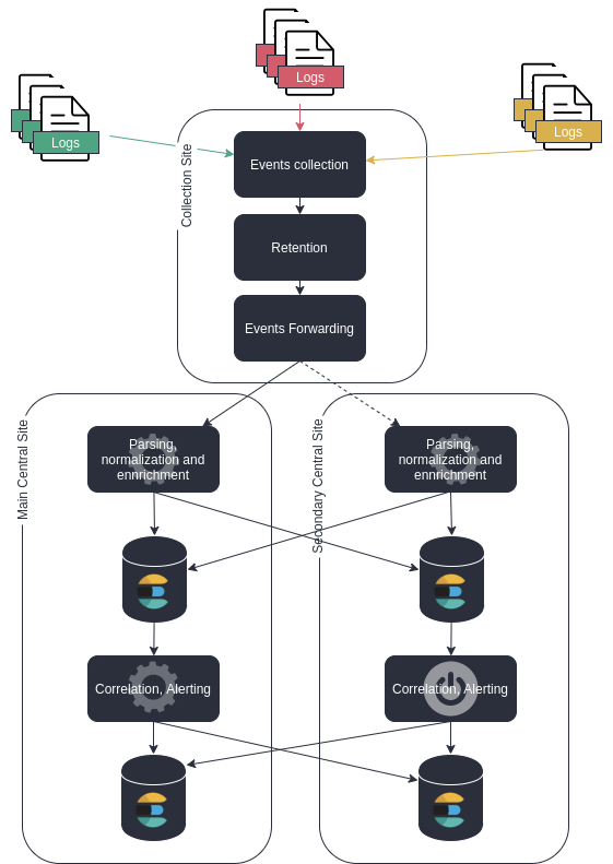
Key highlights
-
Here we have an active/active reception/processing stage, and an active/standby correlation/detection stage to avoid duplicate events generation.
-
Processing load is balanced on the two sites. If the source of events are capable of automatic failover or loadbalancing on a couple of target adresses, then it is easy to switch off the main site for failover
-
activation of the failover site "detection/correlation stage" is manual to avoid impact of "split brain" with
duplicate alertsthat an automatic activation could lead to. -
outputs of the "detection/correlation stage" are also pipelined to the failover site to achieve full matching history on both sides.
-
the events are absolutely the same on both sites (including unique ids), allowing to compare exactly databases content when doing failover validation tests*
The queuing/punchlines view
First, have a look at the reference architecture for a standard log management site.
The Y pattern
Each time a data must be processed/output in multiple directions, we have a Kafka queue to ensure both data protection and independent consuming for all purposes
Now let's have a look at the higher number of queues that we need for dual-site forwarding in a "processing+correlating/alerting" context:
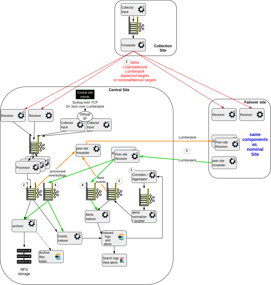
This leverages much more queues of course:
(1) The collector site(s) forwarding layer can be configured to send the logs to the central site when available, and to switch automatically to the failover site if the central site receivers are not reachable.
(2) We have the need, whenever processed events (parsed/normalized/enriched logs) or alerts (detections coming from Elastalert rule engine, scored and normalized as Punch alert events), to go through a Kafka additional layer, in order to both :
- index the record locally into Elasticsearch,
- forward the data to the peer site for remote indexing.
(3) The forwarded events comes with all metadata (unique id, target index name) so as to guarantee it will be indexed into the "same" elasticsearch index on both sites, will not create duplicates on either and allow full comparison of queries on either sites to help validate or periodically test the failover site data consistency.
(4) We have kafka queues just at the receiving stage of the events coming from the peer site. This allows very fast transmission of any message available in one of the queues to be forwarded ((2)), even if the actual indexing on the remote site is unavailable or slower. These queues are consumed for local archiving/indexing by the same tasks in charge of archiving/indexing the locally-produced events/alerts.
(5) The "aggregation/detection/correlation stage" is active on the main site, and not started on the failover site to avoid creating duplicate aggregation/detection/alert events.
Key points
- Although we increase the number of kafka topics due to forwarding, you'll notice that on any given site, the overall storage used is still the same on each site, as compared to a single site. This is because the additional queues or only on the receiving side (so when an avent/alert is produced on a site, it takes storage space on the peer site kafka (which has less processing-output storage used, because it did not produce the record).
- The replication is not only for indexing but also for archiving if you want to have long-term storage replicated on the fail-over site. Note that actual files may differ on both sites if you do this at application level (because of different grouping of documents in batche files). If you decide to use a low-level replication daemon(e.g. rsync) to directly send the same files to the peer site, then you'll need to have application replication of the "archives index" records produced by the main site, so as to allow the peer site to use Punch archives housekeeper and archive extraction tools that rely on this "archives files metadata".
Centralized monitoring of multiple sites
Monitoring an end-to-end collection/central-processing/indexing solution implies potentially complex/evolving monitoring rules (Have a look at What to monitor) .
To avoid having to design many custom rules in the central monitoring system, Punch provides prepackaged micro-services that automatically compute and synthesize technical health status of platform and deployed applications in the platform.
This allows the high-level external monitoring to rely on synthetic status, not needing many rules, relying on small REST-accessible documents. See:
forwarding needs
The platform health monitoring service needs to run on each site, to be able to access all the punchplatform framework clusters on this site. To have centralized view of the status of all sites platform, it is needed to forward the results of this monitoring to the central site.
The channels health monitoring service needs to run on a site that provides an Elasticsearch centralizing metrics and events from the platform (operator command events logging, shiva clusters events logs, punchline metrics). Collection sites most often do not have a local Elasticsearch, as they are often lightwight sites, with as few local operation action as possible. So to have a centralized view of end-to-end health of the channels punchlines/applications, is is needed to forward to a central site all monitoring records from each remote site and record them in the central Elasticsearch. Then the health monitoring service can run centrally to provide the health of all sites applications.
Last, for troubleshooting/capacity management purpose of all site, is is useful also to forward all platform metrics (captured by metricbeat daemon) to the central site Elasticsearch database.
standard monitoring chain pattern
See the multi-sites centralized monitoring Reference Configuration for the typical components and and punchlines for this forwarding and health computation.
2-nodes vs 3-nodes for high-availability of small collection site
The usual requirements, and the 3 nodes answer
-
A production-grade collection site has often the following roles:
- ensure high availability (against single failure) of the reception input port for incoming flows
- forward to a central site
- ensure retention of the data, when communication with central site is not available, with retained data protection against loss in case of single failure
-
Additionally, it is often expected that such a remote collection site (LTR) has less local operation actions, being:
-
monitored from a central site
- requiring no immediate action in case of single failure
- requiring no action to forward "stuck" data once a node failure has been repaired.
Now have a look at how a 3-node setup answers to this.
The 2-nodes temptation
Sometimes, physical constraints (e.g. hosting in a customer-provided existing pair of servers) will prevent a 3-nodes cluster. Of course, this prevent any highly available zookeeper clusteror kafka cluster on these 2 servers.
So the architecture proposed by the designer is often:
- Two fully independent software stacks (1 per server) composed of an input punchline, a local kafka retention queue, and an output punchline.
- A virtual-IP management by an OS-level daemon (like on the 3 nodes version, but clustered on the 2 nodes only). As on the 3-nodes version, this daemon will activate the VIP on one of the 2 nodes, and only if the input port is opened (i.e. the listening process available).
This delivers the base service (managing the retention, allowing availability of real-time forwarding when one server is fully down).
But this variant has also the following differences, as compared to the 3-nodes one :
-
Because the 2 stacks are independent, it is unpractical to have a replication of the retained data between the nodes: If you forward to each-other for safe keeping, then the peer-node copy will never be forwarded automatically anyway in case of failure of the original receiving node (otherwise it would lead to double sending of all logs in a nominal situation). So either you do not replicate, or using this replica for retrieving the data in case of loss of a node while untransmitted data exists implies manual incident-management to activate a "failover" forwarding that will forward data from the
backup copyon the remaining node -
In case of a single node failure, all retained data not already transmitted will not be transmitted until the node is repaired (and lost if the node storage is corrupted) If the node is down more than the configured queue retention time (e.g. 7 days), then the untransmitted data may be erased upon restart before it has been transmitted (automatic purge of old data)
- In case of a
forwarderstage failure on theactiveserver, no transmission will occur until a technical operator comes and fixes the situation. This could occur for example due to a networking issue on the outgoing interfaces of this node. - In 2-nodes variant, you can have a
split-brainof the VIP-management cluster, leading to the VIP being published by the 2 nodes at the same time. This can lead to networking issues on the input flow. - The overall needed cumulated storage space is the same for 3 or 2 servers
- Each server in the 2-nodes variant needs potentially to have 100% more RAM/cpu capacity than in the 3-nodes variant. This is because in the 3-nodes variant, 2 nodes will have to do the queuing management and forwarding (ciphering/compression) when 1 node is down. Whereas in the 2-nodes variant, 1 node will have to process the whole node if the other one is down.